Basic Setup
First Connection with iChidori-Crest
Overview
This guide covers the initial connection of the iChidori-Crest to a Window PC, installing required software, and performing basic configuration of the mosaic-G5 receiver using Septentrio RxControl.
The setup establishes a connection to the receiver, configures the antenna mode where supported, and enables GNSS data output on the receiver's serial ports.
By the end of this article we will have:
- Connected the iChidori-Crest (mosaic-G5 receiver) to RxControl
- Use the appropriate antenna mode for the board variant.
- Enabled NMEA messages output on COM1
- Enabled SBF output on COM2
- Saved all settings as boot configuration
Software Requirement
Install the following software on the Windows PC:
- Septentrio USB Driver — required for Windows to recognize the mosaic-G5 receiver.
- Septentrio RxTools — Software suit to control and monitor your GNSS receiver
Download RxTools and the ossociated documentation from the official Septentrio page: https://www.septentrio.com/en/products/gps-gnss-receiver-software/rxtools
Note
In the scope of these guide series, we primarily use RxControl and SBF Analyzer for the mosaic-G5 receiver's evaluation.
Connect the iChidori-Crest to the PC
Connect the iChidori-Crest to the Windows PC using a USB Type-C cable.
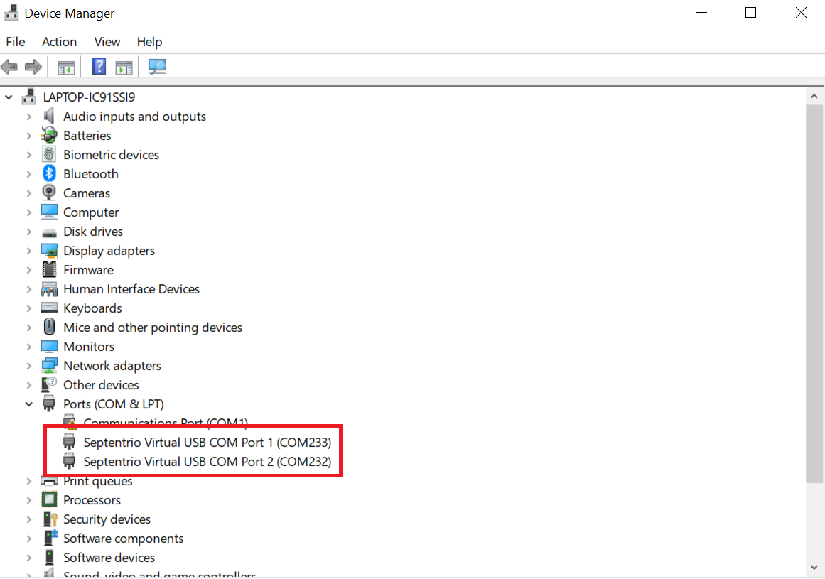
After connecting the board, open Device Manager and check that the mosaic-G5 receiver's USB serial ports are detected.
Connection Troubleshooting
If the expected ports do not appear, check the USB connection and confirm that the Septentrio USB driver is installed correctly. If necessary, reconnect the board or try a different USB Type-C cable that supports data transfer.
Connect RxControl to the Receiver
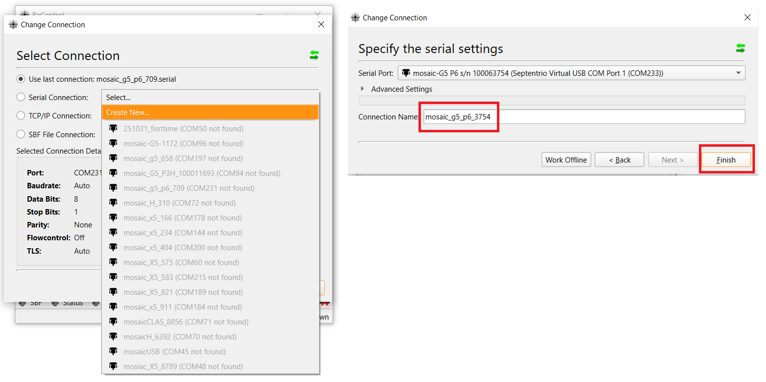
Once the USB ports are detected, create a connection in RxControl. On first launch with a new mosaic-G5 receiver, follow these steps to create a new connection:
- Open RxControl application
- Select File → Change Connection
- Select Serial Connection → Create New → Next
- Under Select Port, choose the receiver's USB port. In this setup, select USB Port 1
- Enter a Connection Name — for example:
mosaic_g5_p6_3754 - Click Finish to create the connection
The receiver should now be accessible through RxControl.
Confirm and Configure The Antenna Mode
The mosaic-G5 supports single-antenna and dual-antenna operation. The available modes depend on the iChidori-Crest variant.
Variant support
- P1, P3: Single Antenna only
- P3H, P6: Single Antenna and Dual Antenna
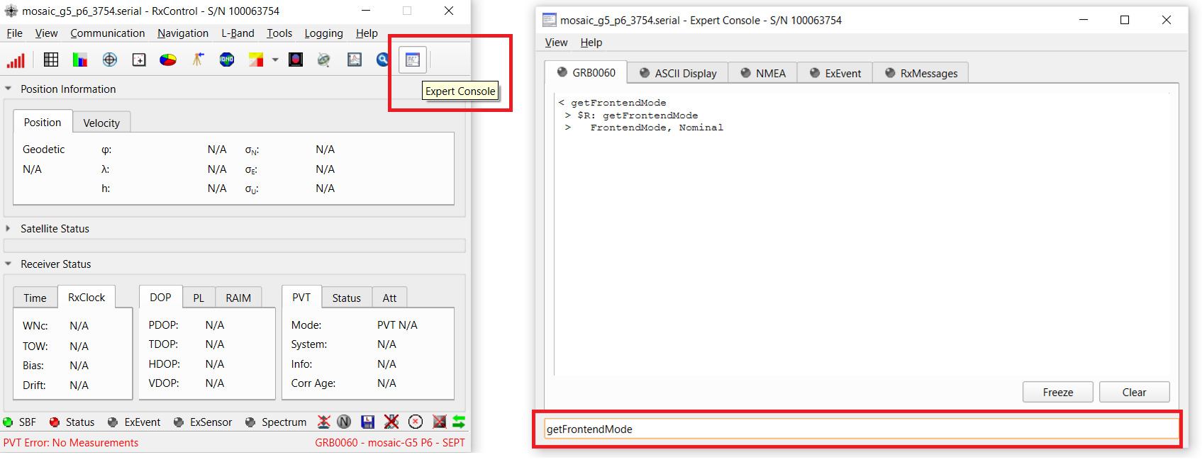
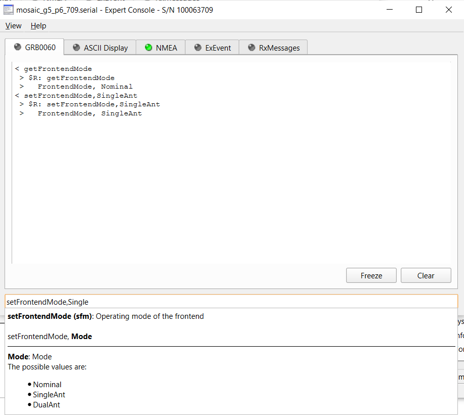
Use the Expert Console in RxControl to check the current mode and configure the receiver if needed. Open the Expert Console from the RxControl toolbar and enter the following commands individually. Choose the mode appropriate for the board variant and antenna setup.
getFrontendMode— query the current antenna modesetFrontendMode, SingleAnt— configure single-antenna mode at the next rebootsetFrontendMode, DualAnt— configure dual-antenna (heading) mode at the next rebootexeCopyConfigFile, Current, Boot— save the configuration to the boot fileexeResetReceiver, Hard, none— reboot to apply
Note
The antenna mode takes effect after the receiver is restarted. If a mode change is required, save the configuration and restart the receiver after completing the remaining settings.
Enable - COM1, COM2 Output
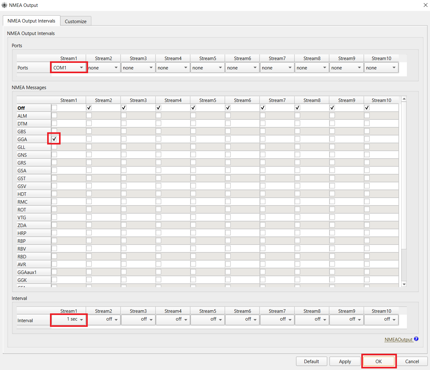
Output NMEA GGA on COM1 - mosaic G5 on COM1 at 1Hz.
Open Communication → Output Settings → NMEA Output. Configure on Stream 1:
| Field | Value |
|---|---|
| Port | COM1 |
| Message | GGA |
| Interval | 1 sec (1 Hz) |
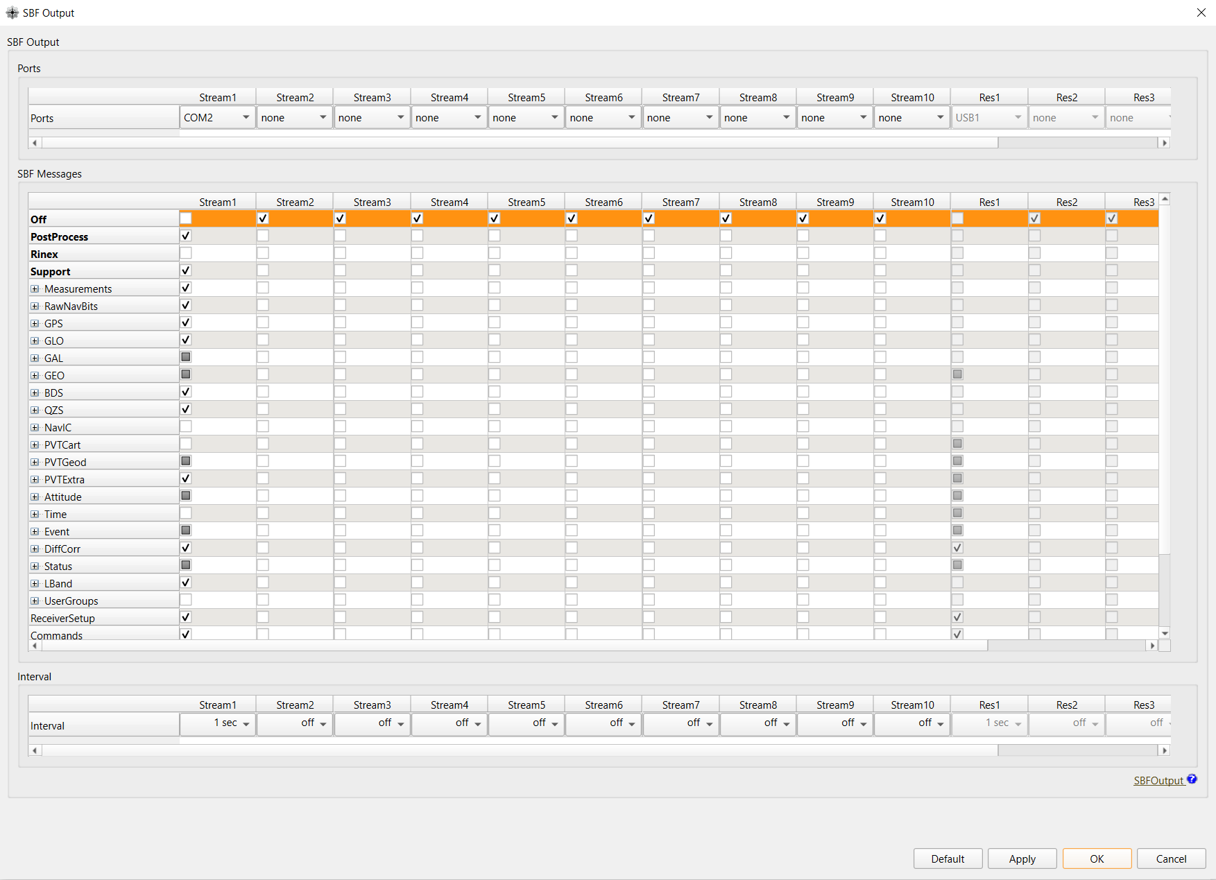
Enable SBF Output on COM2 - mosaic G5 on COM2 at 1 Hz.
Navigate to: Communication → Output Settings → SBF Output. Configure on Stream 1:
| Field | Value |
|---|---|
| Port | COM2 |
| Blocks | PVTGeodetic, MeasEpoch,... |
| Interval | 1 sec (1 Hz) |
Save The Boot Configuration
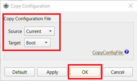
After completing all settings, save the full configuration so it is restored after every power cycle.
To save the current configuration as boot configuration, open File->Copy Configuration, and select Current as source, Boot as target. Click Apply and OK to save.
Warning
Always save to Boot configuration after any change. Settings not saved to Boot will be lost after power cycle.
Optional — Configure the GPIO LEDs
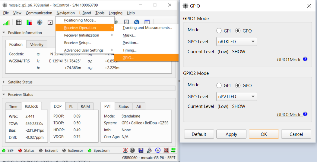
The iChidori-Crest provides two onboard LEDs controlled by GPIO1 and GPIO2 of the mosaic-G5. These indicators can help monitor receiver status during evaluation and field testing.
| GPIO | Function | Description |
|---|---|---|
| GPIO1 | nRTKLED |
LED ON when RTK Fixed |
| GPIO2 | nPVTLED |
LED ON when PVT solution available |
Open Navigation → Receiver Operation -> GPIO, set each GPIO to the corresponding function, then save to Boot configuration.
Summary
In this article, we completed the first connection of the iChidori-Crest to a PC using Septentrio RxControl. Starting from a fresh setup, we established a USB connection to the mosaic-G5 receiver, confirmed and setting the antenna operating mode, configured the receiver to output data on COM1 and COM2. All settings were saved to Boot configuration to ensure they persist across power cycles.
These output streams will be used for the next evaluation, where we explore RTK positioning and data logging on this GNSS receiver.
In the next guide, we will configure the iChidori-Crest as an RTK Rover using RxControl.