Interfaces
40-Pin Header (J1)
iChidori-Crest connects to the Raspberry Pi via the standard 40-pin GPIO header.
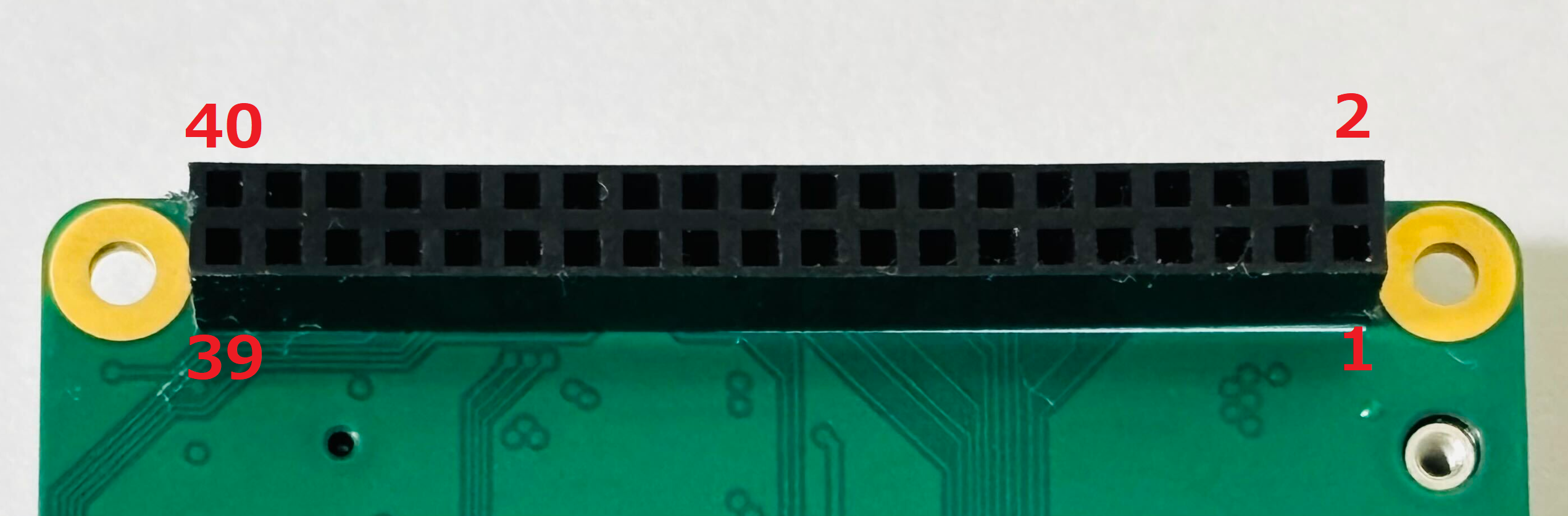
Connector type: 2×20, 2.54 mm Pin socket
Mating connector: Raspberry Pi 4/5 Model B built-in 40-pin GPIO header
40-Pin GPIO Header Assignments
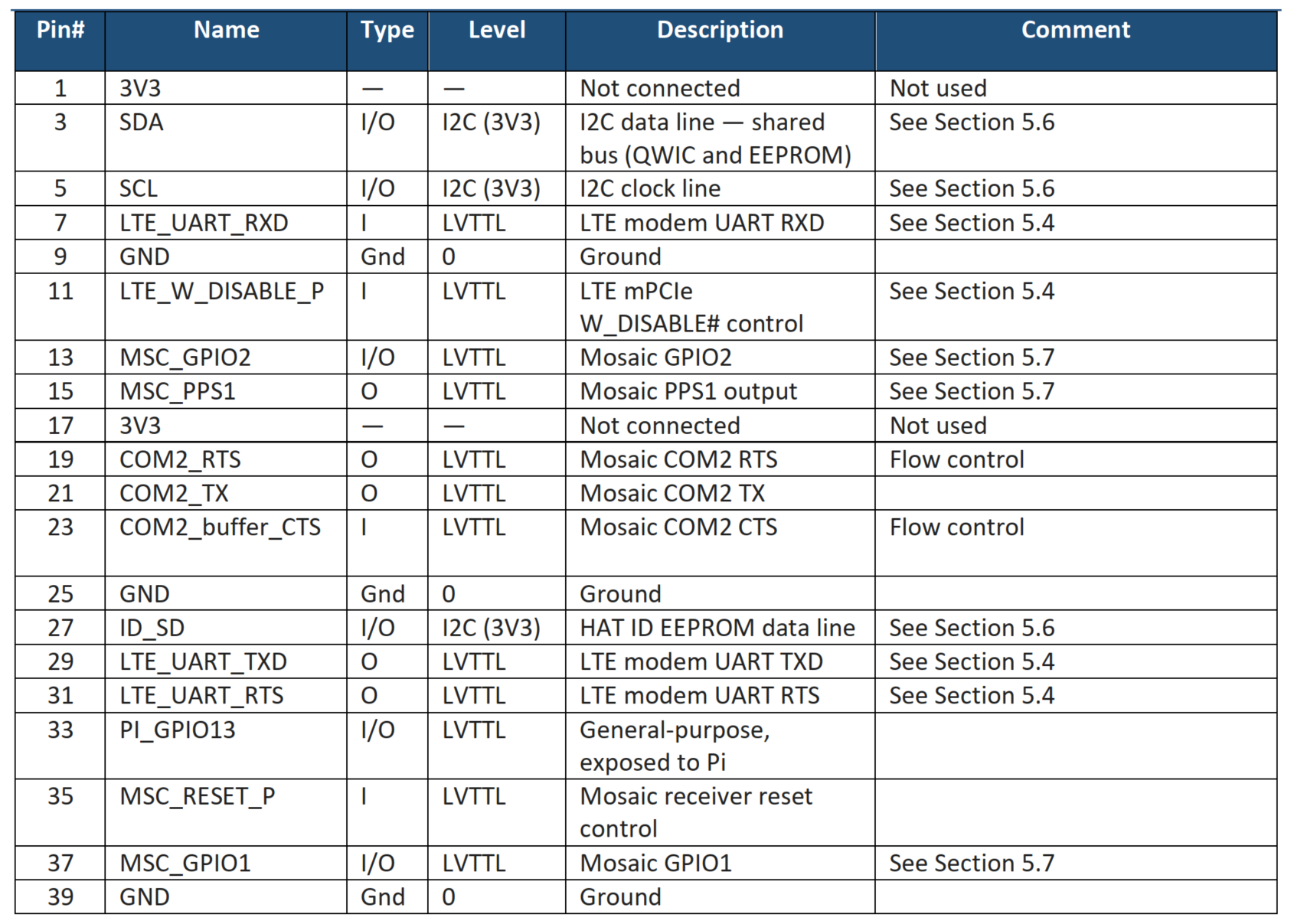
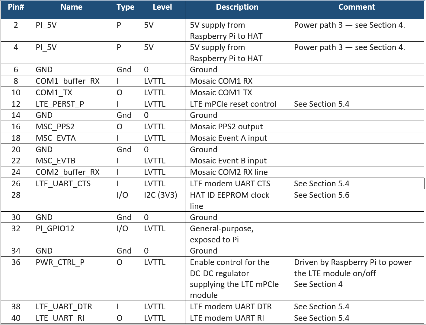
UART Interfaces Summary
| Interface | Raspberry Pi | Mosaic G5 | LTE Module |
|---|---|---|---|
| G5 UART | UART0/1 (GPIO14/15) | COM1 | — |
| G5 UART | UART4 (GPIO8/9/10/11) | COM2 | — |
| LTE UART | UART3 (GPIO4/5/6/7) | — | UART |
Serial port configuration
Raspberry Pi 4/5 has UART0–UART5, but most are disabled by default and require additional configuration.
To enable UART on GPIO14/GPIO15 (TXD/RXD) for mosaic-G5 COM1:
- Run
sudo raspi-config - Select Interface Options → Serial Port
- Set Login shell over serial → No
- Set Serial port hardware → Yes
- Exit and reboot
After reboot, verify which UART type is assigned to the primary serial port:
On Raspberry Pi 4/5, /dev/ttyAMA* represents PL011 UARTs and /dev/ttyS* represents the mini UART.
Use a PL011 UART (/dev/ttyAMA*) for communication with the mosaic-G5.
PL011 UARTs have a dedicated clock and provide stable baud rates at higher speeds. The mini UART (/dev/ttyS0) shares the CPU clock and is not recommended for GNSS applications.
If serial0 points to /dev/ttyS0, reassign it to PL011 by adding the following line to /boot/firmware/config.txt:
This disables Bluetooth and frees the PL011 UART for GPIO14/GPIO15. Reboot and verify again:
Confirm that serial0 now points to /dev/ttyAMA0 before proceeding.
Power Pins
| Pin | Function |
|---|---|
| 2, 4 | 5V from Pi |
| 6, 9, 14, 20, 25, 30, 34, 39 | GND |
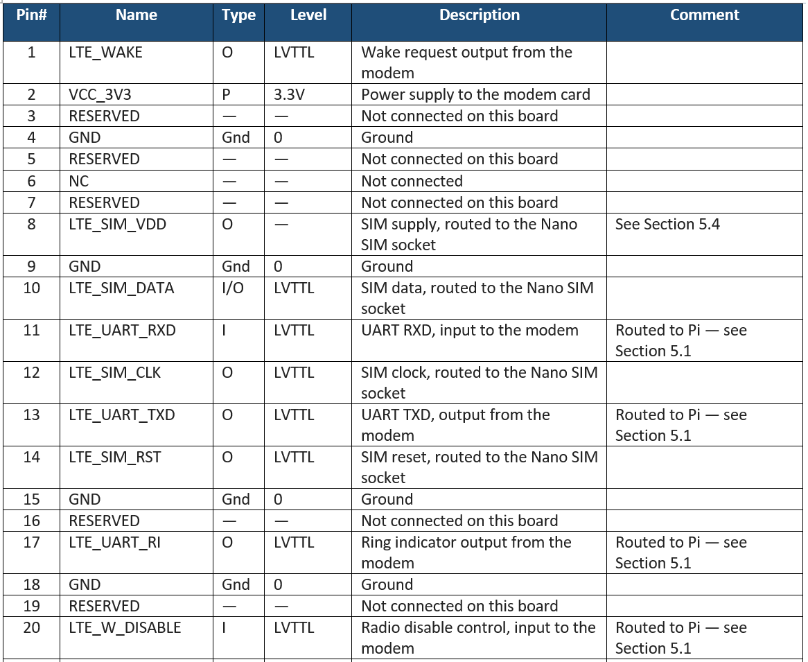
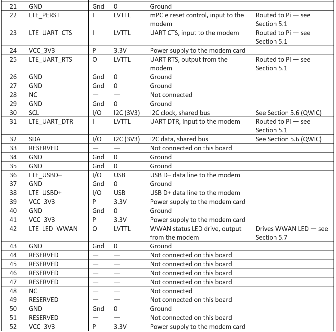
52-Pin mPCIe Slot (J2)
iChidori-Crest provides a standard Mini PCIe (mPCIe) slot for LTE modems.
| Connector | Attend Technology 119A-80A00-R02 |
| Type | 52-pin Mini PCIe edge connector, 0.8 mm pitch |
| Retention | 119A-NUT-80-R02 standoff nut, secured with M2×0.4 screw, 4.0 mm length |
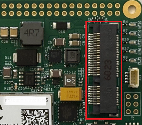
52-Pin mPCIe Assignments
Expansion 6-Pin Header (J8)
Connector type: Conn_01×06, 2.54 mm pin header
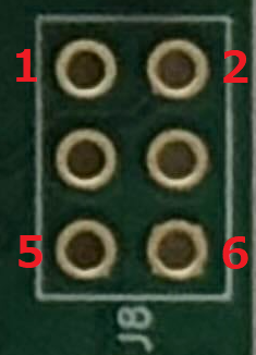
| Pin | Signal | Description |
|---|---|---|
| 1 | PI_GPIO13 | Raspberry Pi GPIO13 |
| 2 | LTE_WAKE# | LTE modem wake signal (active low) |
| 3 | PI_GPIO12 | Raspberry Pi GPIO12 |
| 4 | +3V3 | 3.3V power |
| 5 | WP | EEPROM Write protect |
| 6 | GND | Ground |
USB device Interface (J5)
Connector type: USB Type-C, USB 2.0
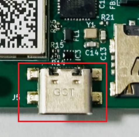
The USB-C connector serves as the primary power supply and data interface.
An internal 2-port USB hub routes the single connector to two independent device interfaces:
| Port | Connected Device |
|---|---|
| 1 | Mosaic G5 USB device interface |
| 2 | LTE mPCIe USB device interface |
GNSS Antenna Connectors
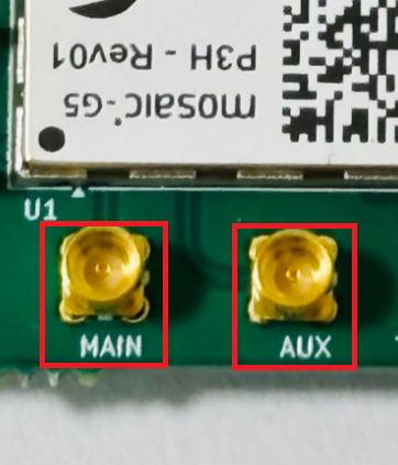
iChidori-Crest provides two MMCX antenna connectors for the mosaic-G5 receiver.

Antenna supply voltage
Both ports supply V_ANT = 3.3 V DC to power active GNSS antennas.
Antenna Mode Setting
iChidori-Crest is offered in variants that differ in antenna capability:
| Variant | Antenna Mode |
|---|---|
| P1, P3 | Single-antenna only |
| P3H, P6 | Single-antenna or dual-antenna (heading) |
Use the following commands to check or configure the antenna mode:
getFrontendMode— query the current antenna modesetFrontendMode, SingleAnt— configure single-antenna mode at the next rebootsetFrontendMode, DualAnt— configure dual-antenna (heading) mode at the next rebootexeCopyConfigFile, Current, Boot— save the configuration to the boot fileexeResetReceiver, Hard, none— reboot to apply
Connect an active antenna to ANT_1 (MAIN). The ANT_1 input is DC-biased and ESD-protected; an active antenna can be connected directly without additional components. Leave ANT_2 (AUX) open when operating in single-antenna mode.
SD Logging (J4)
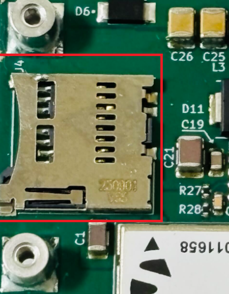
A physical SD card slot is provided for direct on-board logging by the mosaic-G5 receiver.
Note
This SD logging capability is intended for evaluation and debugging purposes only; it is not recommended for use in production/deployed systems.
SIM Card (J10)
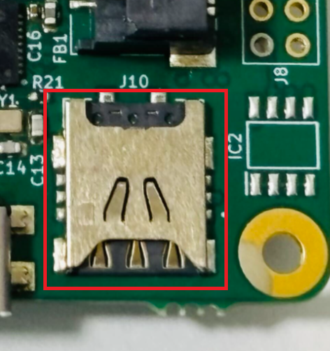
The board provides a Nano SIM socket for the LTE module.
SIM slot on the LTE card
If the installed LTE card has its own SIM slot, the SIM can be inserted directly into that slot instead of the Nano SIM socket on the iChidori-Crest. This allows SIM sizes other than Nano (for example Micro or Mini, depending on the card) to be used. The supported SIM types therefore depend on the LTE card in use.
QWIIC Connector (J11)
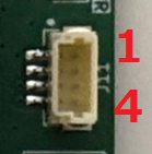
A QWIIC connector is provided for expansion I2C communication.
| Pin | Signal |
|---|---|
| 1 | GND |
| 2 | 3.3V |
| 3 | SDA |
| 4 | SCL |
Back: ← Overview
Next: Specifications →
Quick Navigation
-
Home
Welcome and project overview -
Getting Started
Step-by-step setup from unboxing to first fix -
Application Examples
RTK, data logger, RxTool experiments -
Troubleshooting
Common issues and fixes